- 您现在的位置:买卖IC网 > Sheet目录2000 > IDT5V49EE904NLGI8 (IDT, Integrated Device Technology Inc)IC PLL CLK GEN 200MHZ 32VFQFN
IDT5V49EE904
EEPROM PROGRAMMABLE CLOCK GENERATOR
CLOCK SYNTHESIZER
IDT EEPROM PROGRAMMABLE CLOCK GENERATOR
13
IDT5V49EE904
REV P 092412
Programming the Device
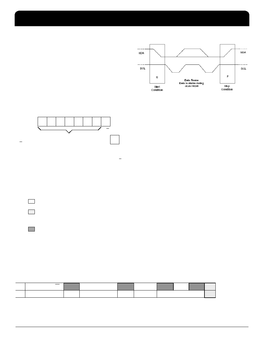
I2C may be used to program the IDT5V49EE904.
– Device (slave) address = 7'b1101010
I2C Programming
The IDT5V49EE904 is programmed through an I2C-Bus
serial interface, and is an I2C slave device. The read and
write transfer formats are supported. The first byte of data
after a write frame to the correct slave address is interpreted
as the register address; this address auto-increments after
each byte written or read.
The frame formats are shown in the following illustration.
Framing
First Byte Transmitted on I2C Bus
External I2C Interface Condition
Progwrite
Progwrite Command Frame
Writes can continue as long as a Stop condition is not sent and each byte will increment the register address.
1
0
1
0
1
0
1
MSB
LSB
R/W
ACK from Slave
R/W
0 – Slave will be written by master
1 – Slave will be read by master
The first byte transmitted by the Master is the Slave Address followed by the R/W bit.
The Slave acknowledges by sending a “1” bit.
7-bit slave address
KEY:
From Master to Slave
From Master to Slave, but can be omitted if followed by the correct sequence
Normally, data transfer is terminated by a STOP condition generated by the Master. However, if the Master still wishes to communicate on the bus, it can
generate a separate START condition, and address another Slave address without first generating a STOP condition.
From Slave to Master
SYMBOLS:
ACK - Acknowledge (SDAT LOW)
NACK – Not Acknowledge (SDAT HIGH)
SR – Repeated Start Condition
S – START Condition
P – STOP Condition
SAddress
R/W
ACK
Command Code
ACK
Register
ACK
Data
ACK
P
7-bits
0
1-bit
8-bits: xxxx xx00
1-bit
8-bits
1-bit
8-bits
1-bit
发布紧急采购,3分钟左右您将得到回复。
相关PDF资料
IDT821024PPG
IC PCM CODEC QUAD NONPROG 44TQFP
IDT821034DNG
IC PCM CODEC QUAD MPI 52-PQFP
IDT821054PQF
IC PCM CODEC QUAD MPI 64-PQFP
IDT82V3001APVG8
IC PLL WAN W/SGL REF INP 56-SSOP
IDT82V3010PVG
IC PLL WAN 51/E1/OC3 DUAL 56SSOP
IDT82V3011PVG
IC PLL WAN T1/E1/OC3 SGL 56-SSOP
IDT82V3012PVG8
IC PLL WAN T1/E1/OC3 DUAL 56SSOP
IDT82V3155PVG
IC PLL WAN T1/E1/OC3 DUAL 56SSOP
相关代理商/技术参数
IDT5V50009DCG
功能描述:IC PC CLOCK 8-SOIC RoHS:是 类别:集成电路 (IC) >> 时钟/计时 - 时钟发生器,PLL,频率合成器 系列:- 标准包装:39 系列:- 类型:* PLL:带旁路 输入:时钟 输出:时钟 电路数:1 比率 - 输入:输出:1:10 差分 - 输入:输出:是/是 频率 - 最大:170MHz 除法器/乘法器:无/无 电源电压:2.375 V ~ 3.465 V 工作温度:0°C ~ 70°C 安装类型:* 封装/外壳:* 供应商设备封装:* 包装:*
IDT5V50009DCG8
功能描述:IC PC CLOCK 8-SOIC RoHS:是 类别:集成电路 (IC) >> 时钟/计时 - 时钟发生器,PLL,频率合成器 系列:- 标准包装:39 系列:- 类型:* PLL:带旁路 输入:时钟 输出:时钟 电路数:1 比率 - 输入:输出:1:10 差分 - 输入:输出:是/是 频率 - 最大:170MHz 除法器/乘法器:无/无 电源电压:2.375 V ~ 3.465 V 工作温度:0°C ~ 70°C 安装类型:* 封装/外壳:* 供应商设备封装:* 包装:*
IDT5V50013DCG
功能描述:IC CLK GENERATOR LOW EMI 8-SOIC RoHS:是 类别:集成电路 (IC) >> 时钟/计时 - 时钟发生器,PLL,频率合成器 系列:- 标准包装:2,000 系列:- 类型:PLL 时钟发生器 PLL:带旁路 输入:LVCMOS,LVPECL 输出:LVCMOS 电路数:1 比率 - 输入:输出:2:11 差分 - 输入:输出:是/无 频率 - 最大:240MHz 除法器/乘法器:是/无 电源电压:3.135 V ~ 3.465 V 工作温度:0°C ~ 70°C 安装类型:表面贴装 封装/外壳:32-LQFP 供应商设备封装:32-TQFP(7x7) 包装:带卷 (TR)
IDT5V50013DCG8
功能描述:IC CLK GENERATOR LOW EMI 8-SOIC RoHS:是 类别:集成电路 (IC) >> 时钟/计时 - 时钟发生器,PLL,频率合成器 系列:- 标准包装:2,000 系列:- 类型:PLL 时钟发生器 PLL:带旁路 输入:LVCMOS,LVPECL 输出:LVCMOS 电路数:1 比率 - 输入:输出:2:11 差分 - 输入:输出:是/无 频率 - 最大:240MHz 除法器/乘法器:是/无 电源电压:3.135 V ~ 3.465 V 工作温度:0°C ~ 70°C 安装类型:表面贴装 封装/外壳:32-LQFP 供应商设备封装:32-TQFP(7x7) 包装:带卷 (TR)
IDT5V50015DCG
功能描述:IC CLK GENERATOR LOW EMI 8SOIC RoHS:是 类别:集成电路 (IC) >> 时钟/计时 - 时钟发生器,PLL,频率合成器 系列:- 标准包装:2,000 系列:- 类型:PLL 时钟发生器 PLL:带旁路 输入:LVCMOS,LVPECL 输出:LVCMOS 电路数:1 比率 - 输入:输出:2:11 差分 - 输入:输出:是/无 频率 - 最大:240MHz 除法器/乘法器:是/无 电源电压:3.135 V ~ 3.465 V 工作温度:0°C ~ 70°C 安装类型:表面贴装 封装/外壳:32-LQFP 供应商设备封装:32-TQFP(7x7) 包装:带卷 (TR)
IDT5V50015DCG8
制造商:Integrated Device Technology Inc 功能描述:IC CLK GENERATOR LOW EMI 8SOIC
IDT5V50015PGG
功能描述:IC CLK GENERATOR LOW EMI 8TSSOP RoHS:是 类别:集成电路 (IC) >> 时钟/计时 - 时钟发生器,PLL,频率合成器 系列:- 标准包装:2,000 系列:- 类型:PLL 时钟发生器 PLL:带旁路 输入:LVCMOS,LVPECL 输出:LVCMOS 电路数:1 比率 - 输入:输出:2:11 差分 - 输入:输出:是/无 频率 - 最大:240MHz 除法器/乘法器:是/无 电源电压:3.135 V ~ 3.465 V 工作温度:0°C ~ 70°C 安装类型:表面贴装 封装/外壳:32-LQFP 供应商设备封装:32-TQFP(7x7) 包装:带卷 (TR)
IDT5V50015PGG8
制造商:Integrated Device Technology Inc 功能描述:IC CLK GENERATOR LOW EMI 8TSSOP